Before you start
- Make sure the files you want to parse are ingested into a data model.
- Add access capabilities for parsing.
- Configure a location for the engineering diagrams.
-
Set the
mime_typeto application/pdf, image/jpeg, image/png, or image/tiff in CogniteFile. - To test new beta features, select > Enable beta features from the overview page.
Parse a diagram
Choose parsing method
Select the file to parse, and then select Run parsing.
- Tag detection only
- Full diagram parsing (public preview)
Detect and link tags to assets and files in CDF. Use for vector or raster files; supports multi-page files (up to 50 pages per run).
Configure the parsing
Configure asset filters: Use the Assets tab to filter which assets are included in the parsing.Configure file filters: Use the Files tab to filter which files are parsed.Configure text recognition: Adjust the text detection settings to improve accuracy.
Run the parsing
Select Run parsing to process the diagram with your chosen settings.
The parsing starts and processes your diagram. The time required depends on the file size and complexity.
Review parsed diagrams
The parsed diagram has four tabs to verify different aspects of the automatic mappings:| Verification tab | What to verify |
|---|---|
| Tag detection | Map asset and file tags to data that’s already in CDF. |
| Symbols | Verify that the system correctly detected and mapped vectors to symbols. This tab is only available for vector files. |
| Merge | Merge annotations with symbols. This tab is only available for vector files. |
| Connections | Verify that the system correctly connected the symbols. This tab is only available for vector files. |
For vector files, only the first page of the file is parsed. For raster files, you only work with the Tag detection tab.
Tag detection: Map asset and file tags to CDF
- Verify the detected tags and their links. Select one or several tags to verify or reject links.
Orange indicates a suggested link. Blue indicates a verified link.
- Select the plus icon on the toolbar to create a new tag and link it to an asset or file in CDF.
All relevant tags are verified (shown in blue) and correctly linked to assets or files in CDF.
Symbols: Verify vectors as symbols
The path selection and symbol creation behavior in this step is part of Full diagram parsing (public preview).To add symbols to the library, select diagram paths and then select which Asset class and Asset type the selection represents. You can also add the selection as a geometry to an existing symbol.You can select unassigned paths (black) and assigned paths (orange, already linked to a symbol detection) in the same action when you create a new symbol. You don’t need to delete an existing detection first; paths that already belong to another symbol move to the new symbol when you save.If a symbol maps to the wrong asset, select the symbol and then Detach from symbol. Only this instance in this file is detached from the symbol.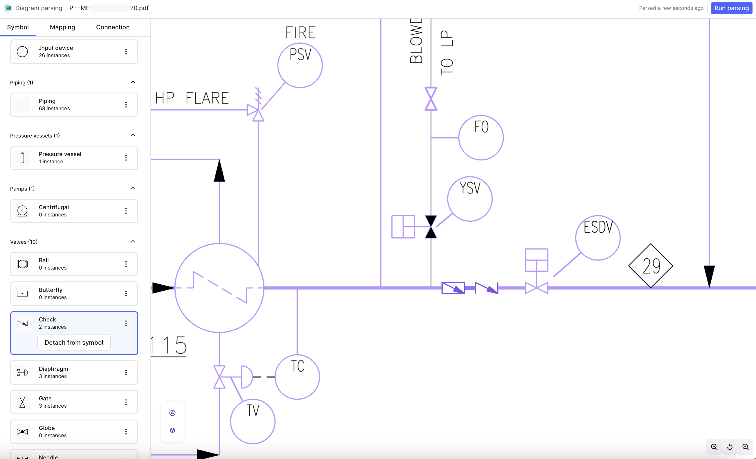
All vectors are correctly identified and mapped to the appropriate symbols in your library.
Merge: Map tags and symbols
Merged tags and symbols appear in blue. For unmerged entities, select the tag and symbol to merge.
Tags and symbols that represent the same entity are merged and displayed in blue.
Connections: Verify connections
Verify that pipes are connected to all connected symbols. If a pipe isn’t detected or incorrect, open the Symbols tab to make corrections. Hover over a symbol to view the entire connection group and select a symbol to view or edit the closest connection.
All pipes and connections between symbols are correctly identified and verified.
Manage parsed output
Use the API to retrieve your parsed output. For more information, see API documentation.Further reading
- Diagram parsing – Overview of diagram parsing and data modeling
- Manage symbol libraries – Create and manage symbol libraries for detection
- Interactive diagrams – Work with diagram data in asset-centric models
- Troubleshooting diagram parsing – Fix common diagram parsing issues