Contextualize mode
Use the Contextualize mode to link 3D objects to equipment to make the twin "smart" and interactive.
Cognite Data Fusion (CDF) supports semi-automatic contextualization of 3D models if the nodes in the 3D model have names that can be related to equipment. We recommend this as the first step to contextualize 3D models.
The next step is to use the Contextualize mode in Cognite Remote to link geometry and equipment manually. Contextualization in Cognite Remote is especially useful for combining and visualizing multiple 3D models, point cloud data, and 360-degree images.
Manual contextualization
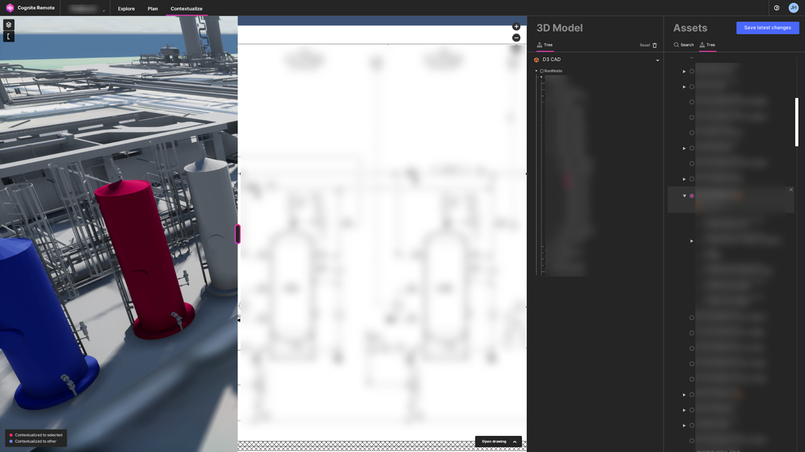
For manual contextualization, you need information about the location of the equipment. This information can, for instance, come from images with visible equipment tags or layout drawings superimposed on the CAD model.
-
First, select the 3D model in the twin that you want to work with. Already contextualized geometry displays in blue color.
-
To contextualize geometry to an asset, go to the Assets panel, and search for the equipment in the asset hierarchy that you want to work with.
You can also switch to the tree view, browse the hierarchy to find the equipment, and select it. If geometry linked to the asset, it displays in pink color.
-
Next, find and click the geometry in the 3D view you want to contextualize to the selected asset. Click already linked geometry to remove a connection.
The 3D Model panel shows the structure of the 3D model with the hierarchy from the original CAD model. As you link 3D nodes to the selected asset, Remote marks them with pink checkmarks in the 3D model hierarchy. The linked 3D nodes also appear in the Asset panel below the asset you're currently working with.
-
To save your contextualization changes, select Save latest changes in the top right corner. Choose to keep or remove the changes in the list of unsaved changes.
When you save the changes, the mappings between the CAD model 3D nodes and the equipment in the asset hierarchy are saved to CDF. The changes take effect for any Cognite application and any custom application built on CDF using the 3D model.
-
Switch back to Explore mode to verify that the equipment is interactive. Click the equipment in the 3D view to open the Details panel and see the related information.
Contextualization tips
-
Use the checkboxes in the 3D hierarchy to add or remove 3D nodes from the selected asset. You can also remove linked 3D nodes from an asset by clicking the X next to their name under the asset in the Asset panel.
-
Colored dots behind the names of collapsed nodes in the 3D model panel indicate contextualized 3D nodes in the sub-hierarchy of that 3D node. Pink dots indicate geometry linked to the selected asset, while blue dots indicate geometry linked to other assets.
-
The Contextualize mode lets you link nodes high up in the 3D model hierarchy to assets. These 3D nodes typically don't have a geometry of their own, but if you link them to the assets, any 3D nodes in its sub-hierarchy that aren't linked to an asset will behave like they're linked to the selected asset. 3D nodes that are indirectly linked to an asset in this way are blue/pink in the 3D view and have a blue/pink checkbox border in the 3D Model panel.
-
Some assets have drawings associated with them, which can be helpful in contextualization work. Select the Open drawing button in the lower right corner to open a drawing side-by-side with the 3D view. You can use the controls to resize and zoom in and out of the drawing.